
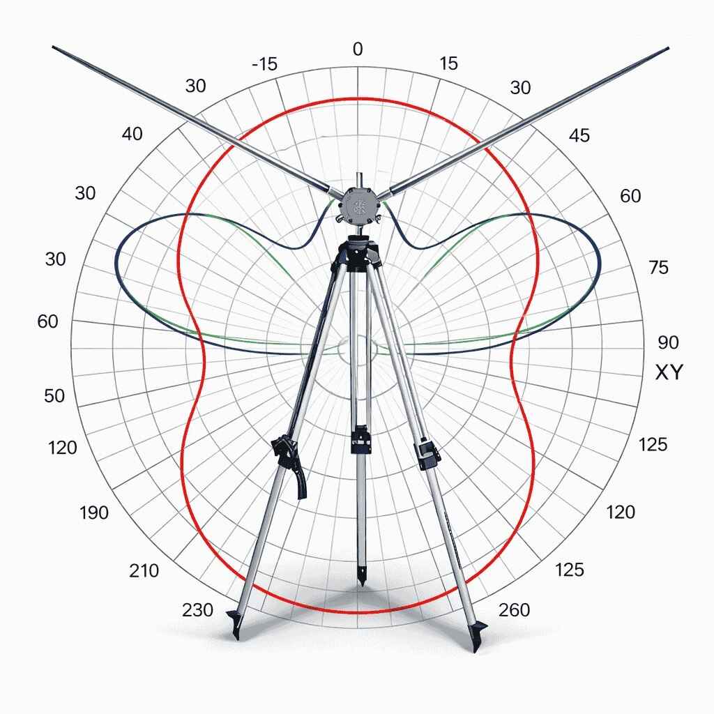
Radiation, Gain, SWR, and Length Behavior of a 120° V-Dipole & Vertical
The Alpha Antenna HexTenna is a modular, multi‑band antenna system designed for portable, field, and base-camp operation. One of its most effective configurations that provides 2.0-2.15 dBi of gain is the Dipole V‑form, where each opposing wire element is set at a defined angle relative to the center hub.
This Data Sheet focuses on the HexTenna optimized with a 120‑degree angle between its two arms—equivalent to each arm being positioned 60 degrees from vertical. This geometry is used because it provides a near perfect 50-ohm balance without the use of a balun in a compact footprint with stable SWR and predictable radiation characteristics, while still delivering ~2.15 dBi gain of a standard horizontal dipole. The 120-degree angle vertical element and counterpoise is also maintained when deployed as a Vertical.
Why 120 Degrees?
A 120° angle is optimized for gain of the HexTenna:
- It preserves the antenna’s orientation, which is central to its design.
- It maintains a consistent radiation pattern across bands.
- It reduces the need for retuning compared to more extreme V‑angles.
- It provides a practical geometry for portable mast‑mounted deployment.
This angle is also mechanically stable and easy to reproduce in the field.
Radiation Pattern Characteristics
General Pattern Behavior
The HexTenna at 120° does not become omnidirectional. Instead:
- The pattern becomes slightly fuller, but still clearly broadside.
- The main lobe tilts slightly upward, improving long‑distance performance.
- Vertical radiation increases modestly, enhancing mid‑angle regional NVIS coverage.
This configuration strikes a balance between DX and regional NVIS communication.
V‑Form (120°) Radiation Patterns
Modeled Values (Representative Across Bands)
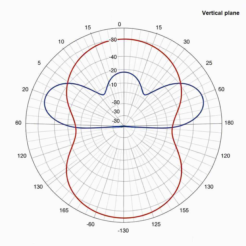
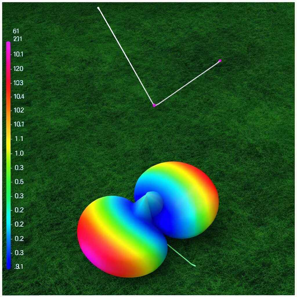
Gain
- Gain: ~2.0–2.15 dBi
- Side Nulls: −2 to −3 dBi
- Main Lobe Angle: ~62–66 degrees
- Beam Width: ~32–36 degrees
Key Observations
- The upward V‑form produces a vertical radiation hump, improving NVIS skywave efficiency.
- Broadside radiation remains strong and well‑defined.
- The pattern is stable and predictable, even in compromised deployment environments.
Performance Characteristics at 120°
- Gain Behavior
Modeling shows that the HexTenna’s gain at a 120° angle remains close to that of a standard straight dipole, with a slight variation due to the upward V‑form.
- Typical modeled gain: ~2 dBi
- Slight upward tilt of the main lobe improves low‑angle radiation, beneficial for DX.
- Side nulls remain well‑defined, preserving directional broadside performance.
Compared to more extreme bends, the 120° configuration avoids the loss of gain seen at narrow angles (e.g., 70–80°) and avoids the pattern distortion seen at very wide angles (150–165°).
- SWR Behavior
The HexTenna exhibits improved SWR at the 120° angle:
- SWR typically trends lower than the *SWR Analysis below, averaging better than the ~1.38:1 of a perfectly horizontal dipole due to improved impedance characteristics of the 120-degree V-Dipole configuration, which can vary based upon ground conditions.
- The vertical V‑form reduces capacitive coupling to ground.
- The geometry remains stable across bands, minimizing the need for retuning.
This makes the 120° in either Vertical or V-Dipole configuration ideal for rapid deployment or emergency operation, by meeting either DX or NVIS mission-based requirements.
*SWR Analysis
Download the Scans for the AntScope application: Download Scans here
| DIPOLE CONFIGURATION
2-40M |
VERTICAL CONFIGURATION
440 Mhz – 20M |
|||
| Band | SWR | Band | SWR | |
| 2 Meters | 1.01:1 | 440 MHz | 1.39:1 | |
| 6 Meters | 1.2:1 | 220 MHz | 1.1:1 | |
| 10 Meters | 1.15:1 | 10 Meters | 1.65:1 | |
| 12 Meters | 1.6:1 | 12 Meters | 1.23:1 | |
| 15 Meters | 1.43:1 | 15 Meters | 1.29:1 | |
| 17 Meters | 1.49:1 | 17 Meters | 1.49:1 | |
| 20 Meters | 1.48:1 | 20 Meters | 1.38:1 | |
| 40 Meters | 1.65:1 | – | – | |
- Electrical Length
As with any bent dipole, the HexTenna’s electrical length changes slightly.
At 120°:
- Required element length increases by approximately 2–3%.
- This is significantly less than the 4–5% increase seen at more extreme bends.
- Once tuned, the HexTenna remains stable without further adjustment.
This is significant reason the HexTenna is favored for real-world deployments.
Vertical vs. Horizontal Components
The HexTenna’s vertical and horizontal components separately reveal:
- Vertical Component:
- Strong downward‑tilted take-off for enhanced low‑angle radiation.
- Beneficial for DX and long‑haul HF operation.
- Horizontal Component:
- Broadside radiation dominance with an NVIS component pattern.
- Pattern width increases slightly, improving coverage without sacrificing gain.
These two configuration options are one of the HexTenna’s defining strengths.
Conclusion
The 120‑degree vertical V‑configuration is one of the most effective and forgiving ways to deploy the HexTenna. It offers:
- Strong gain
- Improved SWR
- Minimal retuning requirements
- Stable radiation patterns
- Balanced DX and regional NVIS performance
The 120° vertical V‑formation of the HexTenna remains the optimal configuration for most operators due to its predictable behavior and ease of deployment.
Appendix B – Specifications & Representations
Specifications
- Power: Full legal limit (1500W PEP)
- RF Connection: SO-239
- Frequency: 2 – 40 Meters, plus 220MHz, & 440MHz
- 80 ounces is the maximum weight when deployed as a dipole
- Packable at a size of 24 x 4 1/2 inches
Representation and Included items
- 2 – 5.41 meter (17′ 9″) telescopic stainless-steel whips are long enough to serve as a Reflector for the Yagi
- 1 – HexTenna™ hub
- 2 – 30/40-meter clip on wire elements
- 1 – 12-20M Counterpoise
- 1 – Top of Mast Mount
CLICK HERE to view the HexTenna Deluxe
